BLDC commutation
To power the motor coils you use a so called H bridge consisting of 6 FET switches allowing the coil currents to power the motor in a well defined 6 stage cycle.
Always two coils are conducting the current. One coil ist “open” or “floating”. Since the motor is spinning the magnets do induct the V_BEMF in the floating coil. We need to monitor this voltage since the zero-crossing of this voltage indicates, that with a delay of electrical 30º degrees the next commutation has to take place.
The commutation cycle goes like this:
| cycle # | Phase A | Phase B | Phase C | current flow |
| 0 | PWM | floating | GND | A to C |
| 1 | floating | PWM | GND | B to C |
| 2 | GND | PWM | floating | B to A |
| 3 | GND | floating | PWM | C to A |
| 4 | floating | GND | PWM | C to B |
| 5 | PWM | GND | floating | A to B |
Since we can not efficiently change the battery voltage to adjust the coil current we do apply the full battery voltage in a pulsed form and use pulse width modulation (PWM) to do so.
The above mentioned cycle can be seen in the following graph:
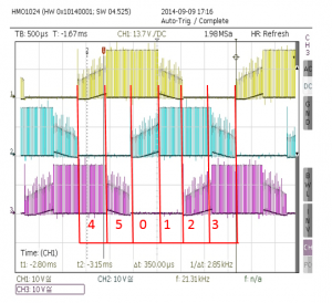
You can see the three phases A, B and C. The PWM frequency I use is between 16kHz and 20kHz. The higher the “smoother” the motor runs but the higher all the power losses due to additional switching losses in the FET switches.
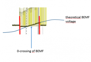
During the float phases of the coils the BEMF voltage can be seen as well. It can not go below -0,3V since the electronics is only powered with +3,3 V and therefore clamps the input. Make sure the on chip input diodes do handle the negative V_BEMF voltage source (otherwise protect with an extra 100k resistor in series). Important is the zero voltage crossing show in a blow up here:
To detect the zero crossing of the V_BEMF there are different possible solutions available. A fast ADC could measure the voltage and trigger the commutation accordingly. I do use three comparators on the STM32F303 chip to release an interrupt to indicate, that a zero crossing took place. So a very basic circuitry could look like this:
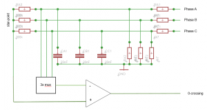
The three phases form with the voltage divider a “star-point” or “virtual ground”. This is the one reference to the comparator (positive input). The V_BEMF itself is divided to a level that the STM32F303 can handle. In addition a low pass filter eliminates the ugly 16kHz-20KHz common mode voltage induced from the power chopping (PWM). An earlier design of mine based on an ATmega-8 8-bit microprocessor and used a multiplexer that applies the correct V_BEMF to the neg input of the comparator depending of the commutation stage.
That does work. But not well. The RC low pass provides a phase-shift of the comparator-signal and causes commutation timing errors. At full throttle (PWM 100%)the average coil current with a LiPo4S battery will be at around 12A (9000 rpm). You do not want a commutation error then. The BLDC motor power with 12A*15V = 180W will set the motor on fire, burn your FETS and unscrews the motor…. I know what I am talking about 😉 .
In the SW the commutation cycle can look like this:
void commutationPattern(uint8_t step) {
	//too fast changes of the speed / pwm setting can cause out of sync. so allow only max pwm steps per cycle
	if (newPWM < (setPWM - 2)) { setPWM -= 1; TIM1->CCR1 = setPWM;
		TIM1->CCR5 = setPWM + compWindowOffset;
	} else if (newPWM > (setPWM + 2)) {
		setPWM += 1;
		TIM1->CCR1 = setPWM;
		TIM1->CCR5 = setPWM + compWindowOffset;
	} else {
		setPWM = newPWM;
	}
	//waitForCommutation means that a comparator event has been detected the commutation can happen after the 30deg delay (timer 3)
	if (step == NEXT && waitForCommutation == 1) {
		if (commutationStepCounter < STEP_5)
			commutationStepCounter++;
		else
			commutationStepCounter = STEP_0;

		switch (commutationStepCounter) {
		case STEP_0:
			commutateNow_0();
			break;
		case STEP_1:
			commutateNow_1();
			break;
		case STEP_2:
			commutateNow_2();
			break;
		case STEP_3:
			commutateNow_3();
			break;
		case STEP_4:
			commutateNow_4();
			break;
		case STEP_5:
			commutateNow_5();
			break;
		}
	} else {
		waitForCommutation = 0;
		switch (step) {
		case STEP_0:
			commutateNow_0();
			break;
		case STEP_1:
			commutateNow_1();
			break;
		case STEP_2:
			commutateNow_2();
			break;
		case STEP_3:
			commutateNow_3();
			break;
		case STEP_4:
			commutateNow_4();
			break;
		case STEP_5:
			commutateNow_5();
			break;
		}
	}
}
With NEXT == true the next commutation step will be executed. A too fast PWM increase/decrease can cause the controller to get out of sync. So I do only allow a certain max PWM change in one cycle (a 7th mechanical turn). Its still fast enough…
At low speeds the V_BEMF gets very low and is difficult to detect. TO start a BLDC motor one should know the position of the motor magnets to the coils to start the commutation at the right step. I at the moment start the motor by forcing a hard coded pattern to the motor until it got some speed an switch then to the closed loop mode. Thats not nice and it takes some tuning and will only work for some motors and needs to be adjusted for other motors types. There are some other approaches where as you measure the inductance by current pulses applied to the three coils (see “Ressources”).
A typical BLDC 3 phase output voltage pattern looks like this:
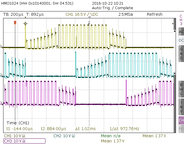
You can see the voltage peak each time the ground pulling FET switches to high impedance (float). A coil does everything to keep the current flowing, so the voltage at the coil rises and tries to keep current flow.
The freewheeling diodes of the FET swichtes conduct this current peak away and protects so the FETs.
You can also see during the floating phase of the coils, how the V_BEMF is crossing GND. 30 electrical degrees later, the commutation takes place.